
SF15-T - 1:10
Started: 18.03.2016
Completed: 21.01.2019
Pieces used~ 2290
Days worked: 107
Completed: 21.01.2019
Pieces used~ 2290
Days worked: 107
Construction report
Monocoque
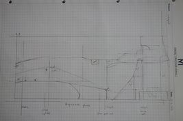
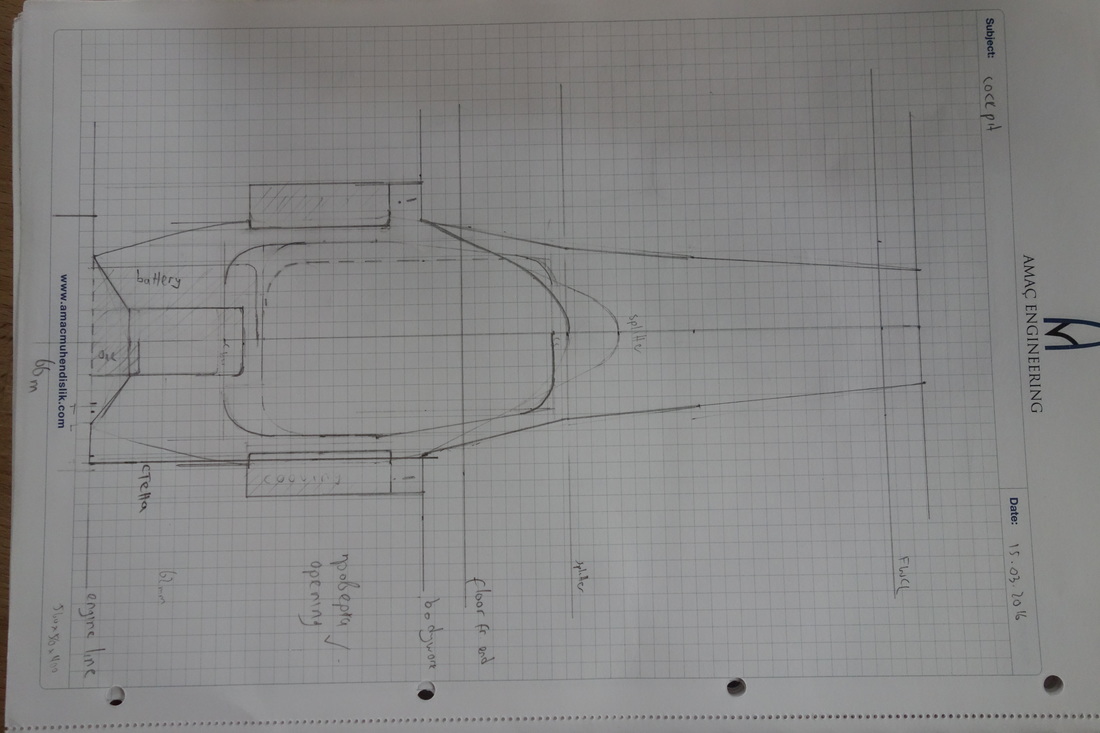
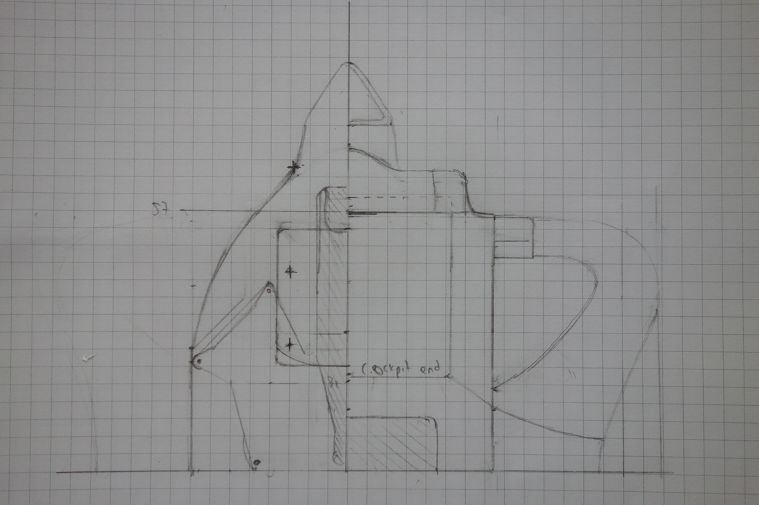
Let us talk about the drawings and collection of information first, as this is a step hugely underestimated in my previous reports. Firstly, I scanned the whole topic on F1T for useful photos and collected them in a folder. Then, I searched specifically for any components not present in my collection. As soon as I’d acquired a good overall impression of the car, I made a side and top view of the whole car. This involved a long search for dimensions, partly in the regulations and also trying to measure them off photos (several of the same thing, shot from different angles, perspective taken into account as accurately as possible). It served as a guide for these more detailed monocoque drawings:
|
|
|
With these drawings, I could proceed to production. My aim was to work very cleanly and neatly. 1:10 is new territory for me, but it turned out to be very pleasant. The first few pics show the basic structure of the monocoque. Something I had to adapt to was the different behavior of cardboard thickness in relation to its size compared to 1:18. It is less stiff (needs more layers), but allows for much more precise sculpting. It’s just like the process of building a carbon fibre road bike – apply material where needed. The front bulkhead, for example, is made up of three layers of cardboard. This layup also ensures much higher stiffness, as glue soaks into the paper fibres and solidifies them.
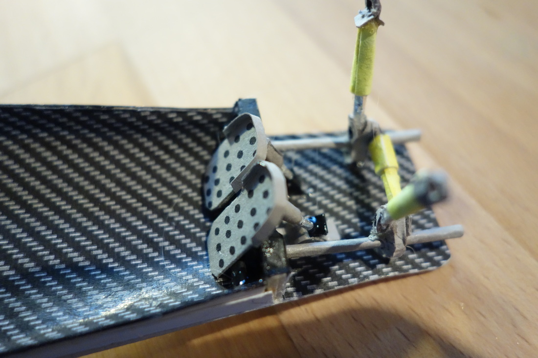
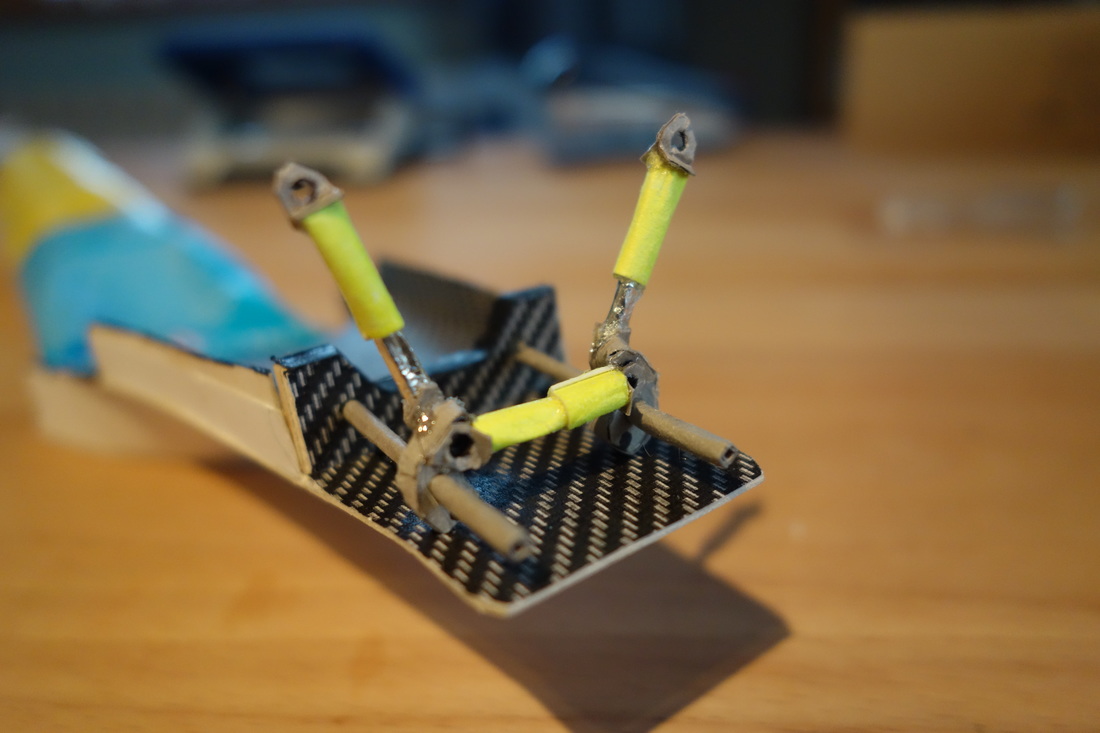
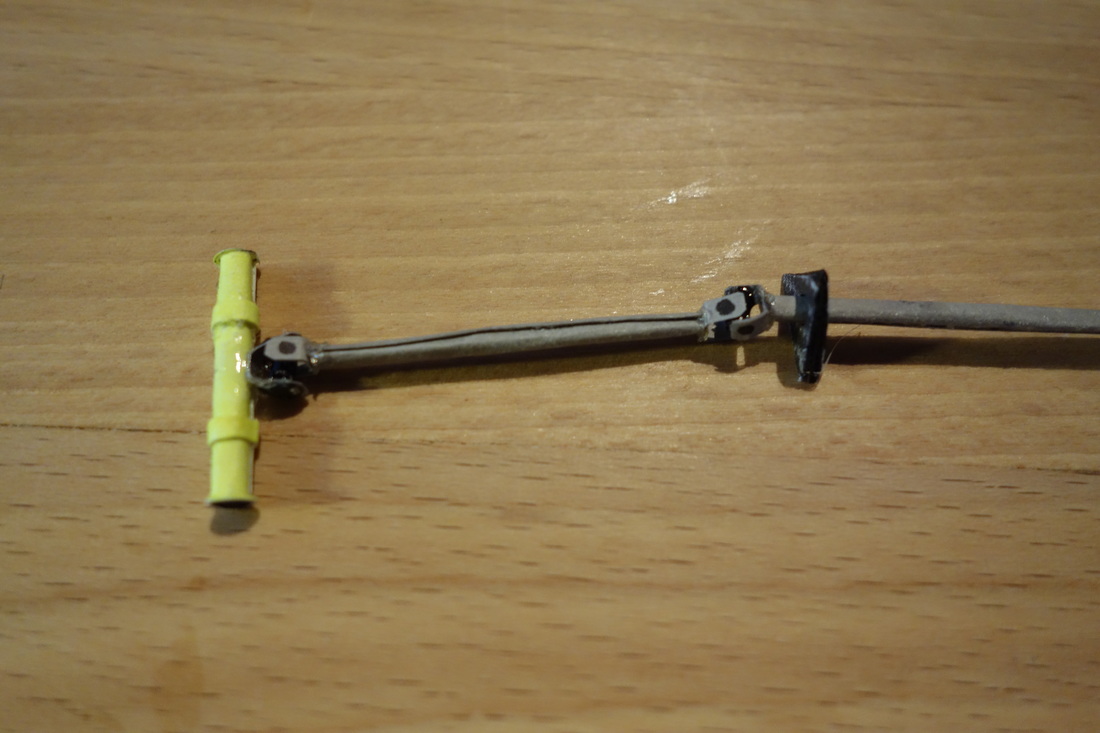
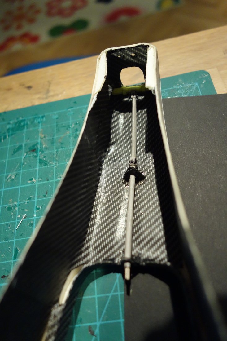
Once the basic shape was complete, I worked on the internals, which honestly was a real pain in the ass. NO specific info is to be found about pedals, steering etc, so it was more or less guesswork. Nevertheless, I gave it my best. Here’s how I built the dampers, rockers, and anti-rollbar. I’m particularly proud of the steering column. I included realistic universal joints, and in addition, the spot where the steering wheel will later be attached came out nicely (the “V” under the windshield). The pedals were even more difficult to figure out.
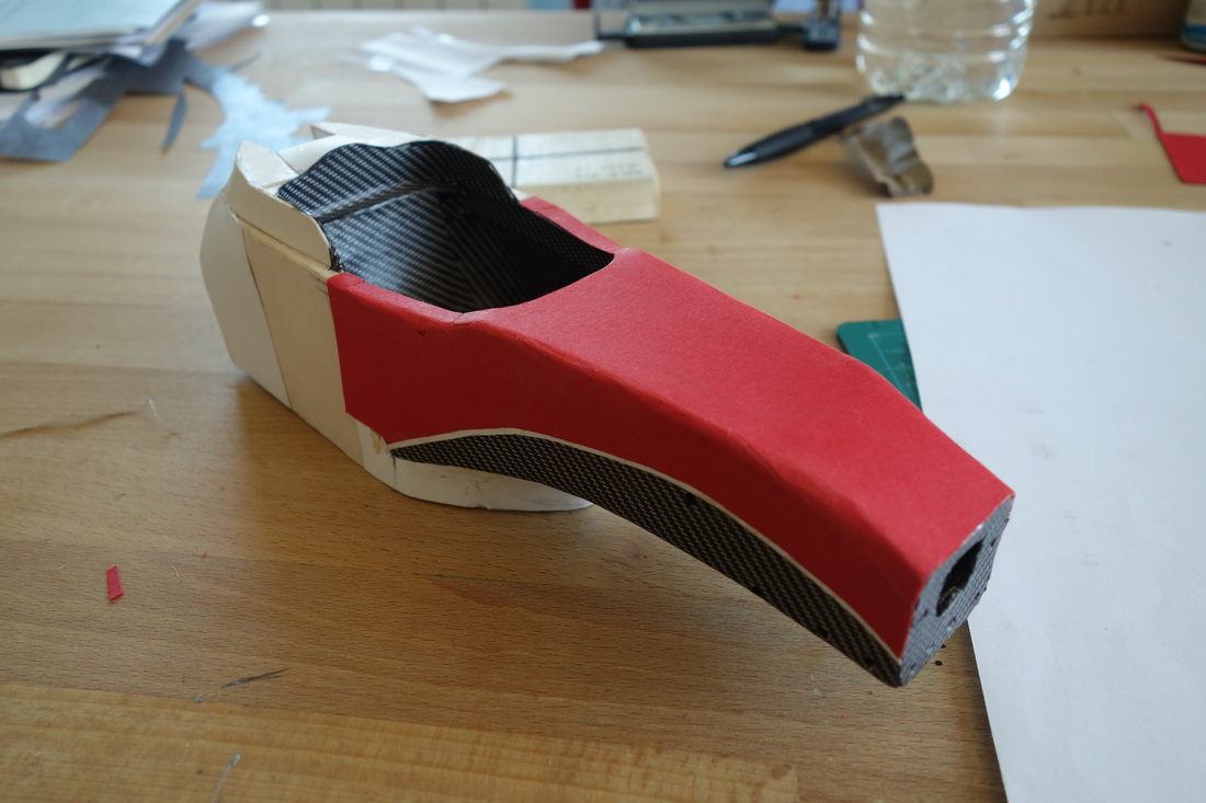
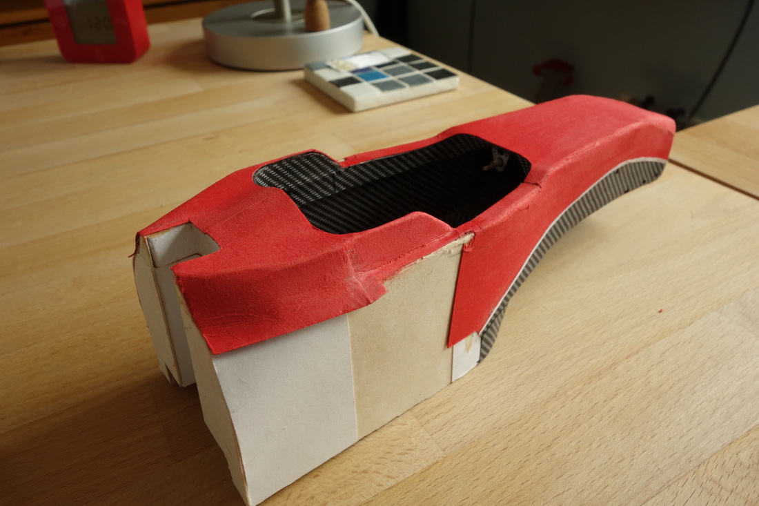
With these bits installed, I could glue the top and bottom half of the monocoque. Here, I used reinforcement angled pieces which I could cut to form a nice fillet. It then got covered with a thin sheet of paper and sanded for a smoother surface and additional stiffness. This allowed me to start working on the outside. I applied the basic red cover – a time-consuming process. It had to consist of one piece only which conforms to curves in different planes. This means that I had to introduce slices which allowed bending but were as unnoticeable as possible. A measure I only reluctantly took, but it couldn’t be avoided. I also added carbon fibre texture and the characteristic white line.
The covering continued around the cockpit opening. Here, the shape defining process was even more complex. Several attempts were made until I arrived at the correct shape, and even then, I had to sand and thin the paper in specific regions so that in the end it sit where it should.
The covering continued around the cockpit opening. Here, the shape defining process was even more complex. Several attempts were made until I arrived at the correct shape, and even then, I had to sand and thin the paper in specific regions so that in the end it sit where it should.
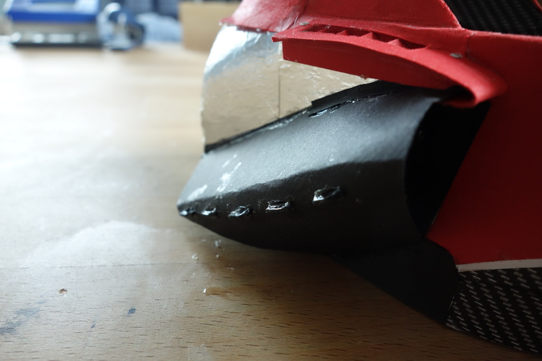
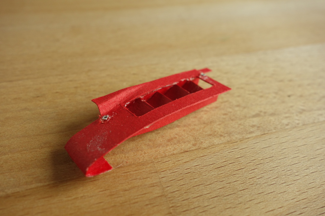
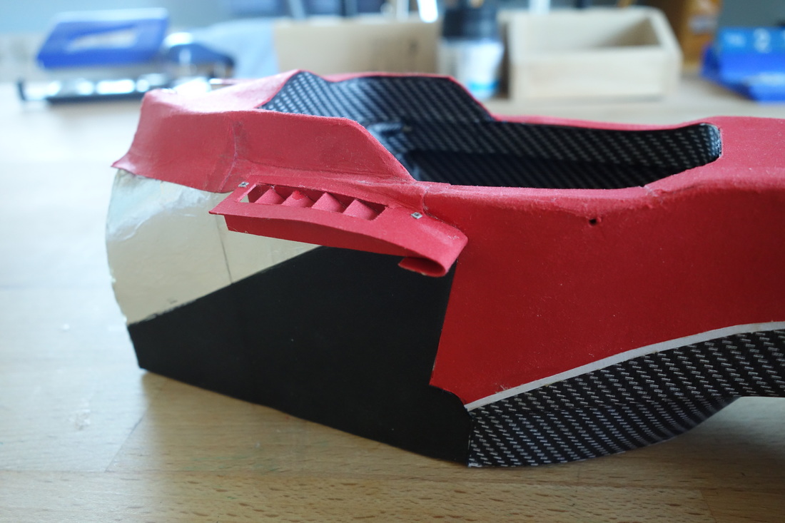
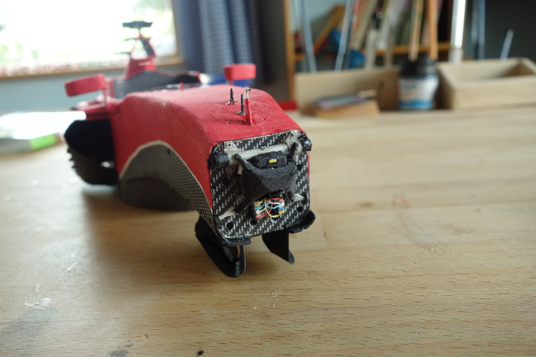
The next step was adding the sidepods’ holders and their cooling gills, as well as the radiator bases with their special cooling winglets. I also applied heat shielding on the sides and back wall of the cockpit, as well as the holes for the engine. Here, I consulted my front view drawing and made an engine positioning jig to make sure the actual one will later fit properly.
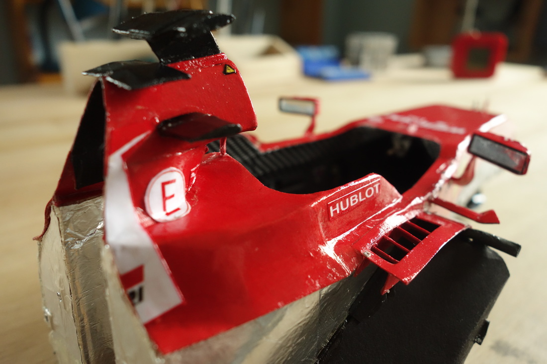
Some small but really satisfying details followed – the rear view mirrors and the fins situated right behind them. Gently bending and sculpting the cardboard, adding screws and sanding to achieve smooth curvatures was enjoyable.
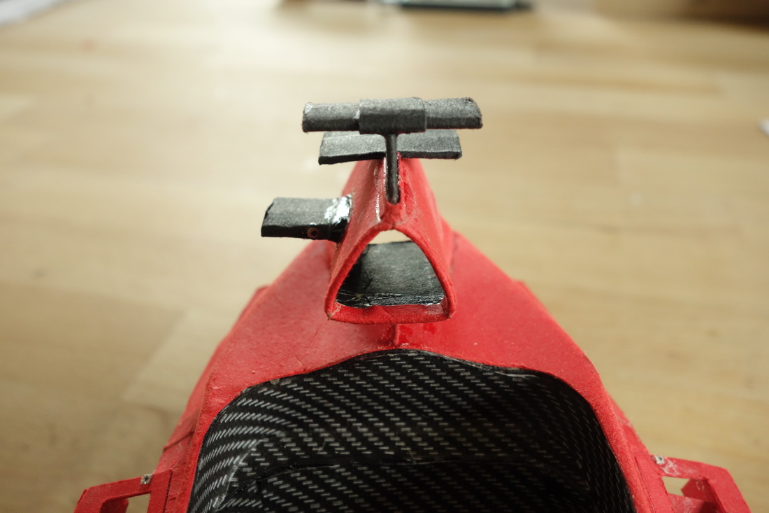
The air box was the final component in this area. Note the additional slot under the big air inlet. This piece is characterized by a complex, two axis curvature. I then added the transponders and TV cameras. Especially the one on the right-hand side turned out nicely, with a beautiful fillet. It also surprised me how stiff the bond is, even though there are no reinforcing elements supporting it.
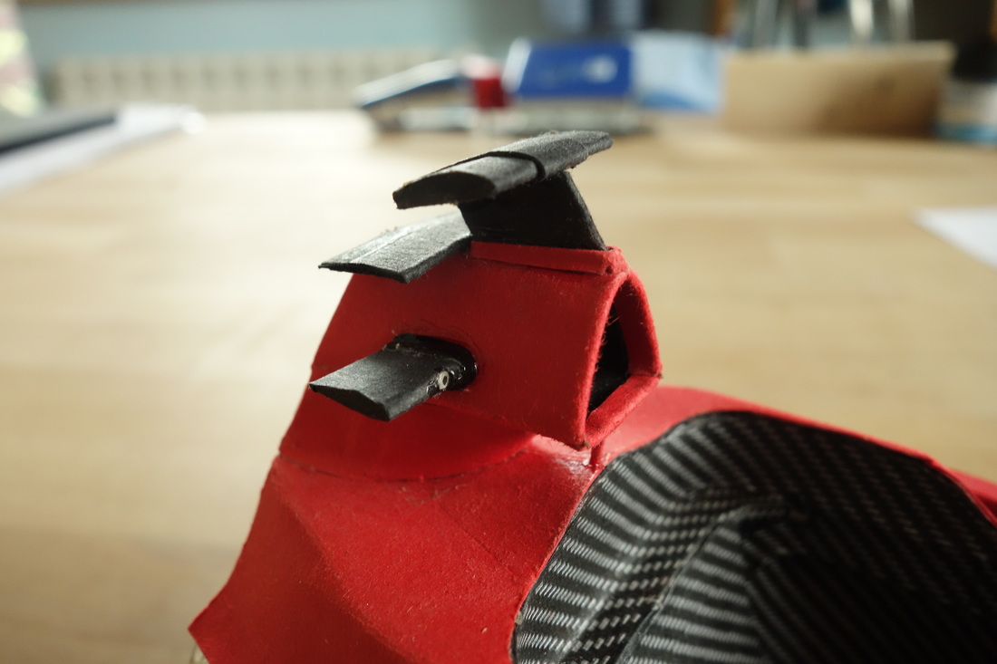
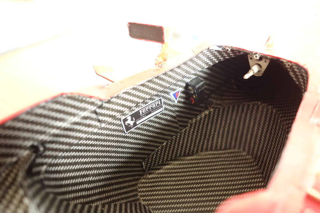
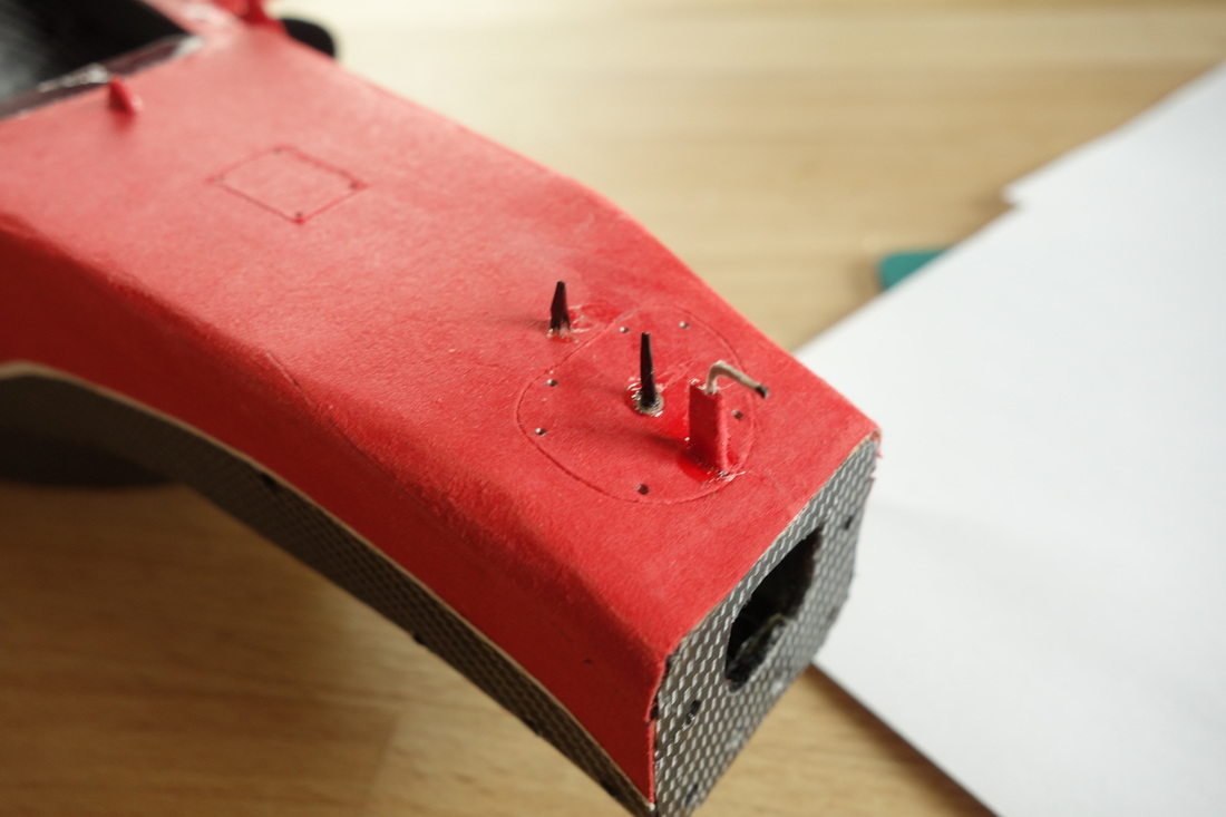
The closing stages of the monocoque build include the cockpit’s internal walls, with some logos and the ignition/switch box. Also, on the top surface: the pitot tubes, suspension adjustment panel, the windshield. And finally, the turning vanes and the front bulkhead details. Pictures of the latter were scarce, but I managed a decent level of accuracy. Some tiny bits were good fun to make and glue.
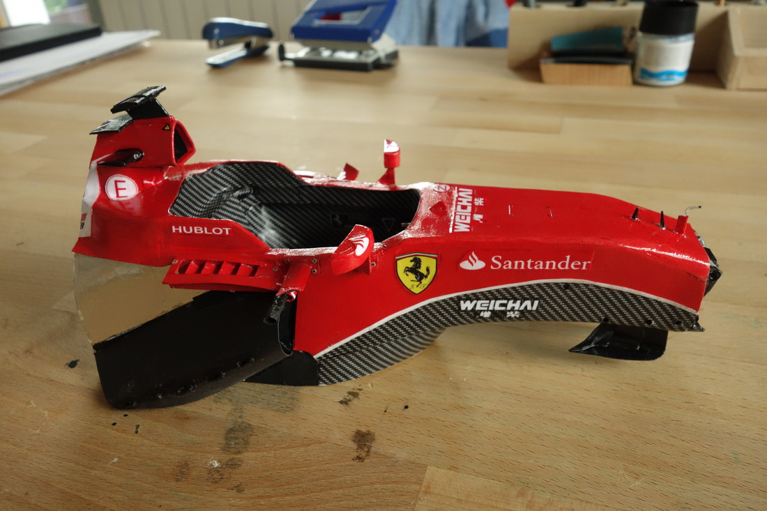
I then sanded all surfaces using my new homemade sanding kit, featuring sandpapers ranging from P400 to P2000. I also made some useful “files”. The decals were pretty easy to find and as usual, I reworked them with Adobe Illustrator. I glued them in place and covered everything with two coats of water-based Marabu varnish. On the following day, I applied further two coats of an oil-based one to achieve a glossy finish. And here is the completed monocoque:
Underbody
I'd like to start with the collection of information. I used primarily pics of areas such as the barge boards, diffuser and other diverse surrounding details. Of course, the main shape conforms to the master drawing, as it has to hold everything in the correct position. And the wooden plank underneath is (as unfortunately for me so few other parts) is defined to the milimetre by the rulebook. So I started with the basic shape. As you can see, the central area where the cockpit and powertrain sit is lower than the periphery, and I was concerned that it would not be laterally stiff enough. Therefore it consists of two layers and is now definitely stiff enough. However, the layering technique is vastly different fron the one I used on the MP4-30, so that now the floor edges are thinner and more realistic.
Having completed the base, I gradually started 'populating' it with details. There really isn't much to say about them. It's just a repetition of looking at photos, designing templates, gluing them in place. A technique worth mentioning that I only recently adopted was the one where I sand the pieces of paper/cardboard to make them fit properly. This is visible if you look at the small black vertical board with two holes (it will later hold the vertical element next to the sidepod panels). Also, I took into account that Ferrari use a different carbon weave for the larger floor surfaces.
Finally, I concentrated on the trailing edge and the underside. The detailig is almost as accurate as it gets. Pay attention to the tiny winglets, the starter hole and the two flaps at the back. The underside is less exciting, you can see the smooth thin black cover and the aforementioned plank with its bolts.
The finished underbody looks like this:
Power unit
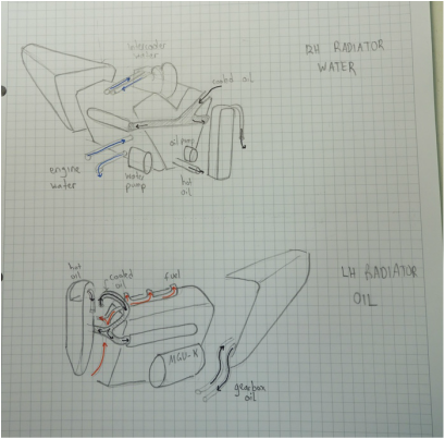
As I’ve said many times this is the area of the car with the scarcest detail available. I spent a lot of time studying photographs trying to figure out what is where. Because the engine is one of these components which determine the positions of many others. You have to get it right, because otherwise the gearbox, cooling, electrical motors and even bodywork might go wrong. Starting with some drawings:
|
|
|
Then, it was all about building a stable and sufficiently stiff main shape block. One aspect I paid attention to were the mounting points to the cockpit and gearbox. You can see the framework, the engine block is actually quite stiff. Once the shape was finalized, I tried to replicate the cast metal look. And finally, the details followed. They were mainly bolts, cooling pipes (a nightmare to figure out – it’s just like trying to trace the beginning and an end of a spaghetti string inside a bowl), drive shaft and some other minor things, such as the water pump. Then, it was onto varnishing. So the finished engine consists of about 140 pieces. Note the oil piping, the water cooling and pump. At the front, there is also the connection for the oil tank. The red pipes are delivering fuel to the engine plenum, which will be installed later.
|
|
|
|
The gearbox followed more or less the same building approach. Still, some words on it. The basic shape is more complex compared to the engine’s. That’s evident when you look at the drawing. Its cross-sections vary constantly, so I decided to use a simple box technique for the front part and a framework for the rear. On the inside, you can see supports for the suspension wishbones, rear rockers (but not hard music fans) and dampers and some heat shielding where the exhaust pipes lead to the turbine. It’s the first gearbox with some internal components. Once the inside was finished, I could enclose the construction with its nicely curved top and its exhaust slot. It then underwent a ‘cow’ stage – this was to ensure that after the cabon fibre coating, no white areas would be visible from underneath. Then, the carbon coating itself. It wasn’t too easy, because I always try to use as few pieces and therefore as few seams as possible. This means that all suspension slots have to be cut in advance and fit perfectly. I then varnished it once and added most details. Some, for example cooling pipes and of course the rear crash structure, are still missing.
|
Next, probably the longest phase followed. Building each and every component from the powertrain. More details are available on F1T, but here is the powertrain once mounted:
|
Nosecone
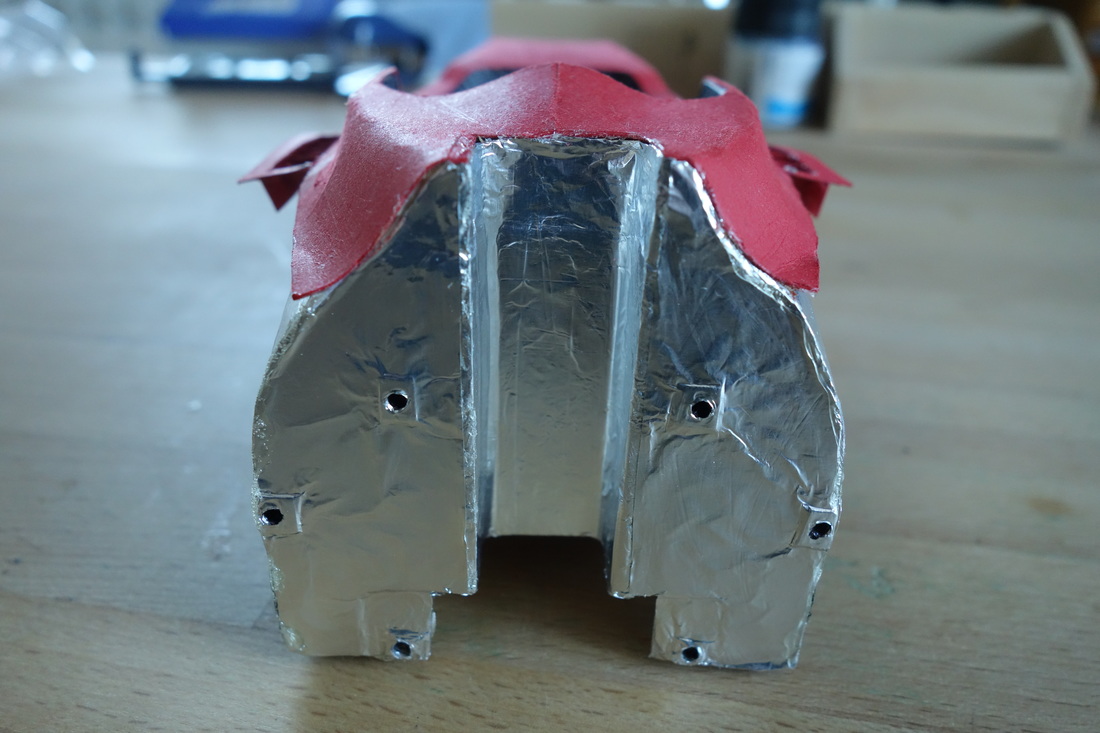
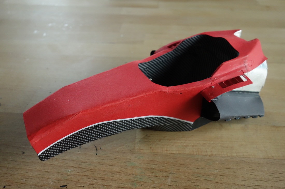
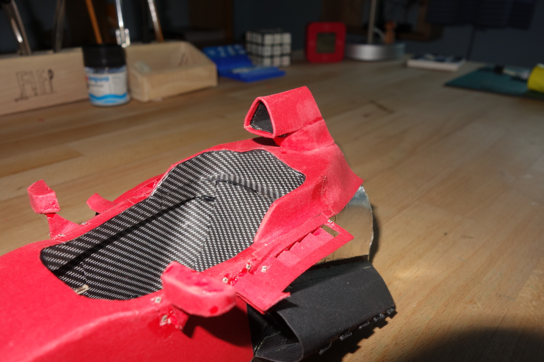
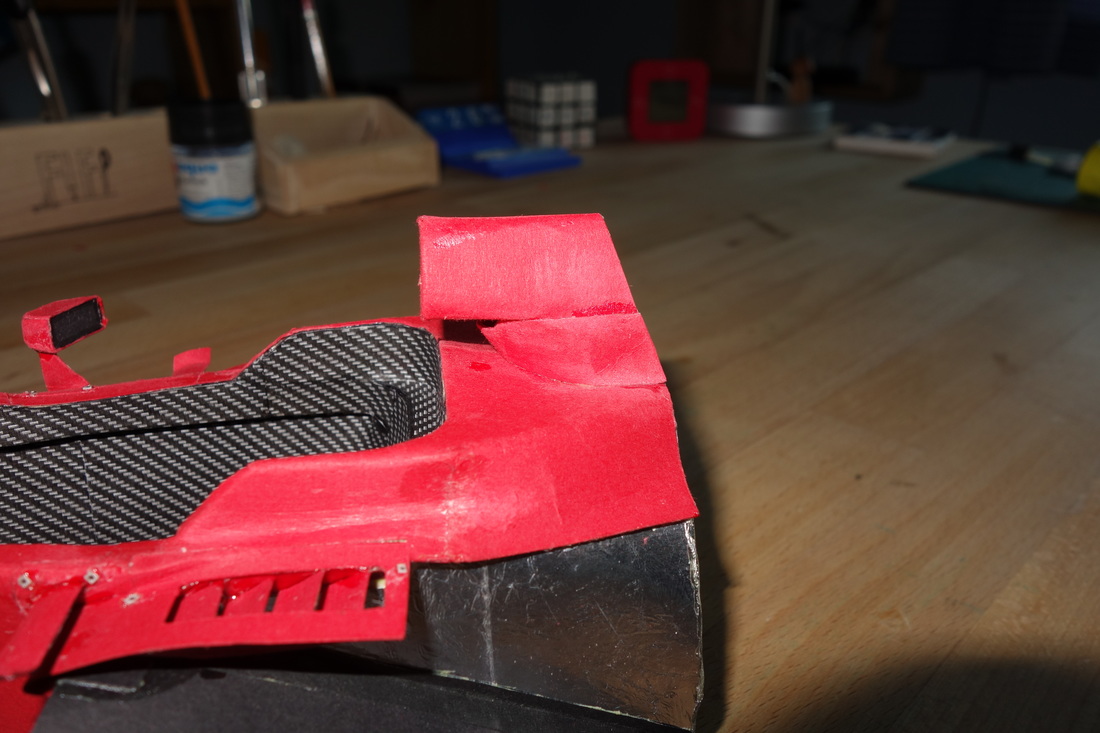
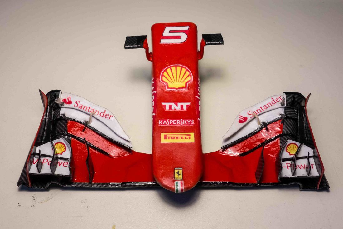
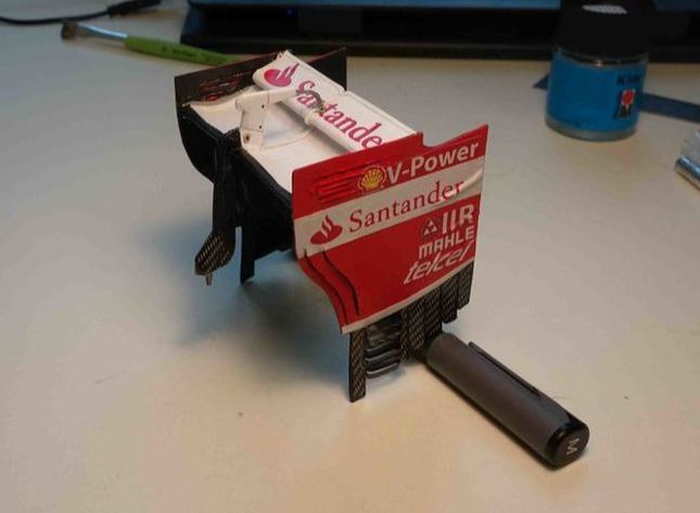
The nosecone is one of the coolest bits to model: one can find tons of pictures, it is a relatively simple piece shapewise, and it's pretty - motivation is high. The first step as with every component is to figure out dimensions precisely. Once that's figured, I have to settle on a concept of how exactly the structure will be built. In this case, the main point is to get the stiffness high between the mounting rods and the FW attachment points. So this very area is a single piece 1mm thick cardboard. To it, the rods themselves are firmly attached. The bottom surface (actually, there is more material underneath, but you'll see it later) is not as thick, it serves the sole purpose of keeping the side plates at the desired distance. It also gives the nose tip its contour. The next step is to get the external shape just right. For that I use a combination of all possible cardboard thicknesses. On the bottom, for exmple, there are two longitudinal spacers on which a curved slightly thicker than normal sheet of paper is glued and curved towards the edges. The top is also a combination of cardboards, the main challenge here is to achieve a perfect curvature. So the top surface is tapered and additional thin pieces fill the gap and allow for bending. With the structure completed, it's on to the next cool bit: colored covers. Here's a tribute to the many stencils that never earn spotlight - the don't get on the car, but it wouldn't exist without them. I managed to get a single piece of red cardboard to cover the whole nosecone, which results in an improved surface quality. I made use of the kaspersky logo on the side: I could allow for a slot there which enabled two-dimentional bending and I could get away with it as the decal hid it later on. Another aspect is sanding: I make my way from P120 through to P1000, which leads to acceptable quality in difficult areas such as the bottom of the nose tip where the cardboard comes from many directions. The type of glue used locally also has an effect on the sanding properties of the cardboard: UHU hart creates a hard sandable block and can be applied on top of already glued bits. Applying the carbon fibre texture is nothing too special. I still need to figure out the shape in advance. And of course, decals finish things up. The finishing touch comes with the tv-cameras. They have a simple structure: a main red cardboard body with a metal rod keeping the shape and serving for mounting to the nose. And the black and carbon ends are purely decorative. I managed to build the nosecone completely hollow, which is more realistic than previous attempts of mine. In general, 1:10 is soo different from 1:18 and it's obvious if you compare this to the MP4-30. |
|
|
|
Front wing
Following the nosecone, the logical next step is the FW. There is nothing too special from a modelling point of view here. I did, however, have to slightly modify the way I build it up in comparison to the previous 1:18 wings. So I started with a base plate (the neutral aerofoil in the middle) which is supported by a metal wire and also holds the rods that attach it to the nose. On top of it came the first three elements (red), based on one whole piece. The current 1:10 scale allowed me to more closely copy the bends in the wing. It's extraordinary how the airflow is directed outward in such a complex, step-by-step manner. |
Suspension
After a substantial period of stagnation, I finally gathered some motivation to go on with my project. The area of the car that had to be dealt with was the suspension. Basically, the general technique remains largely the same as in previous projects. This time, however, the scale gave me the benefit of being able to more precisely replicating the shapes of the wishbones themselves. I could decide, in every single case, weather it is more suitable to use tubes or 2D planks. In both scenarios, though, a metal rod runs through the whole wishbone and at the same times serves as a connector to the chassis. One significant improvement over previous cars was that I managed to build the parts relatively accurately and selected the distance between the two ends of each wishbone to be slightly longer than the corresponding mounting points on the chassis. Thus, I could mount them by gently stretching them and they held themselves in place by slight internal stress. The other benefit of the scale was the fact I could easily wrap the wishbones in carbon, which worked very well on the front and a bit less elegantly on the back.
Of course, as in every component, the initial drawing was critical. To make sure everything would fit together later on, I built a jig that visualizes the axle position and ride height (front and rear). Luckily, suspension pictures are readily available, so this was not that much of a challenge. The more difficult area was of course the rear suspension, but I’ll come to that in a minute and you’ll see why in the pictures. The front suspension was mostly a joy to build. As the wishbones are pretty airfoil-shaped, so I chose to use flat pieces of my second-thickest cardboard (~0,5mm) and then sanded them to shape. Laying the carbon fibre on top of that was easy. Another major improvement are the uprights. Now, I integrated the axle holders. The wishbones attach with a press-fit and the whole assembly remains comparatively compact, so that room remains for the brakes etc. This solution is sufficiently stiff. The front brake ducts worked out wonderfully. Sculpting the air inlets and their curvature was enjoyable. Finally, I assembled the wishbones, pullrods, brake ducts and uprights. Next, I moved to the rear counterpart of that assembly, leaving the brake system for later. The process here is pretty much analogous. The differences are that the wishbones are slenderer, which poses a challenge to the carbon coating. Also, there are a lot more components in a tighter area: apart from the wishbones and pullrod, there’s also the track rod and the drive shaft, all of which have to fit through the rearmost extension of the bodywork.
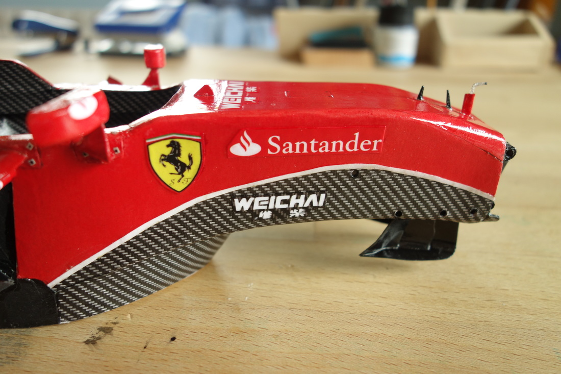
Before I could move on and install all of these parts, I had to build the bodywork area mentioned earlier. This was as much fun as it was a challenge, as is with every piece which is characterized by a complex, multidirectional curvature. I had to cut out several prototypes before I arrived at the final shape. Now, recreating such a curvature means introducing a slot somewhere in the paper blank to enable it to approximately bend in more than one plane. The challenge is to do that in such a way that the slot is hidden in the final product. A trick I use is to look at the decals and try to slot the paper below one of the sponsor logos/transitions, so it gets covered. This time, the transition between the red section and the carbon fibre underside was the perfect spot. Some sanding was required, and after I added the decals and treated the bodywork with my two varnishes, that was the result:
Only then was I able to fit everything together. This was significantly trickier than the front suspension, as most components were overconstrained, having to fit both through the (narrow) bodywork opening and to the gearbox casing mounting points while still remaining properly oriented.
Next, I moved on to the brakes/brake covers. I paid more attention to the front brakes, as their covers are less enclosed and allow more of a view of the finished assembly. As far as detailing is concerned, I built the discs, calipers, mounting support, wheel axle, nut and wheel mounting points. Some internals such as brake fluid pipes, electrical components or exact turning mechanisms are missing, because I really lacked the patience to build something so tiny that would not be visible once the car was completed. The whole assembly was covered with the drums, one relatively simple component with cooling slots and a diameter of 33mm. And the front suspension was complete. A very similar procedure followed for the rear brakes, their calipers are just a bit less detailed. Also, note how the rear axles are not hollow (blown) – they end with a sharp cone. The rear drums are more enclosed. I had to build them from 4 pieces: the main drum cylinder, then a transition cone, then a ring , and finally, another cone facing inwards. In reality, all of this is a continuous rotational piece, but that would be near impossible to make at that scale. Sadly, a picture of the carbon-covered result at that stage is not available (i.e. I forgot), so check it out in the next reports.
After a substantial period of stagnation, I finally gathered some motivation to go on with my project. The area of the car that had to be dealt with was the suspension. Basically, the general technique remains largely the same as in previous projects. This time, however, the scale gave me the benefit of being able to more precisely replicating the shapes of the wishbones themselves. I could decide, in every single case, weather it is more suitable to use tubes or 2D planks. In both scenarios, though, a metal rod runs through the whole wishbone and at the same times serves as a connector to the chassis. One significant improvement over previous cars was that I managed to build the parts relatively accurately and selected the distance between the two ends of each wishbone to be slightly longer than the corresponding mounting points on the chassis. Thus, I could mount them by gently stretching them and they held themselves in place by slight internal stress. The other benefit of the scale was the fact I could easily wrap the wishbones in carbon, which worked very well on the front and a bit less elegantly on the back.
Of course, as in every component, the initial drawing was critical. To make sure everything would fit together later on, I built a jig that visualizes the axle position and ride height (front and rear). Luckily, suspension pictures are readily available, so this was not that much of a challenge. The more difficult area was of course the rear suspension, but I’ll come to that in a minute and you’ll see why in the pictures. The front suspension was mostly a joy to build. As the wishbones are pretty airfoil-shaped, so I chose to use flat pieces of my second-thickest cardboard (~0,5mm) and then sanded them to shape. Laying the carbon fibre on top of that was easy. Another major improvement are the uprights. Now, I integrated the axle holders. The wishbones attach with a press-fit and the whole assembly remains comparatively compact, so that room remains for the brakes etc. This solution is sufficiently stiff. The front brake ducts worked out wonderfully. Sculpting the air inlets and their curvature was enjoyable. Finally, I assembled the wishbones, pullrods, brake ducts and uprights. Next, I moved to the rear counterpart of that assembly, leaving the brake system for later. The process here is pretty much analogous. The differences are that the wishbones are slenderer, which poses a challenge to the carbon coating. Also, there are a lot more components in a tighter area: apart from the wishbones and pullrod, there’s also the track rod and the drive shaft, all of which have to fit through the rearmost extension of the bodywork.
Before I could move on and install all of these parts, I had to build the bodywork area mentioned earlier. This was as much fun as it was a challenge, as is with every piece which is characterized by a complex, multidirectional curvature. I had to cut out several prototypes before I arrived at the final shape. Now, recreating such a curvature means introducing a slot somewhere in the paper blank to enable it to approximately bend in more than one plane. The challenge is to do that in such a way that the slot is hidden in the final product. A trick I use is to look at the decals and try to slot the paper below one of the sponsor logos/transitions, so it gets covered. This time, the transition between the red section and the carbon fibre underside was the perfect spot. Some sanding was required, and after I added the decals and treated the bodywork with my two varnishes, that was the result:
Only then was I able to fit everything together. This was significantly trickier than the front suspension, as most components were overconstrained, having to fit both through the (narrow) bodywork opening and to the gearbox casing mounting points while still remaining properly oriented.
Next, I moved on to the brakes/brake covers. I paid more attention to the front brakes, as their covers are less enclosed and allow more of a view of the finished assembly. As far as detailing is concerned, I built the discs, calipers, mounting support, wheel axle, nut and wheel mounting points. Some internals such as brake fluid pipes, electrical components or exact turning mechanisms are missing, because I really lacked the patience to build something so tiny that would not be visible once the car was completed. The whole assembly was covered with the drums, one relatively simple component with cooling slots and a diameter of 33mm. And the front suspension was complete. A very similar procedure followed for the rear brakes, their calipers are just a bit less detailed. Also, note how the rear axles are not hollow (blown) – they end with a sharp cone. The rear drums are more enclosed. I had to build them from 4 pieces: the main drum cylinder, then a transition cone, then a ring , and finally, another cone facing inwards. In reality, all of this is a continuous rotational piece, but that would be near impossible to make at that scale. Sadly, a picture of the carbon-covered result at that stage is not available (i.e. I forgot), so check it out in the next reports.
|
|
|
|
Rear wing
Building the rear wing is one of the most enjoyable areas of the whole car. That’s because of several reasons: pictures are readily available, the mounting points are already specified and there is enough free room around, no further components depend on it. It is merely a case of letting the fingers loose and detailing as much as possible. Starting with the endplates, the goal is to recreate as many of the aerodynamic slots as possible. This is not easy in areas such as the top leading corner, where I am limited by the thickness of the cardboard (which strictly speaking, is not to scale: 1:10 would mean, in the case of the endplate, a structure with poor stiffness). Still, most of the grooves and dents are present in my model in some form or another. It is very interesting to try and deduce how the aerodynamics experts have tried to direct air both in- and outwards in different areas in an effort to achieve maximum diffuser and wing efficiency. I decided to build the mounting pylon and lower wing as one part to reach maximum stiffness. It was a fun part to sculpt; I approached it similarly to the way I’d build a suspension part. The wing itself is a simple curved airfoil. However, pay closer attention at the front view of the finished wing and you’ll see a curvature along the width axis as well (it is slightly higher where the pylon is compared to the endplate mounting points). All the parts next to each other and the final result (varnished, of course). |
|
|
Bodywork
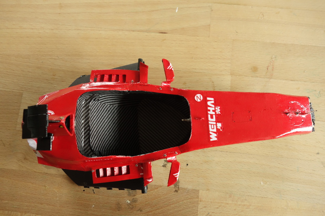
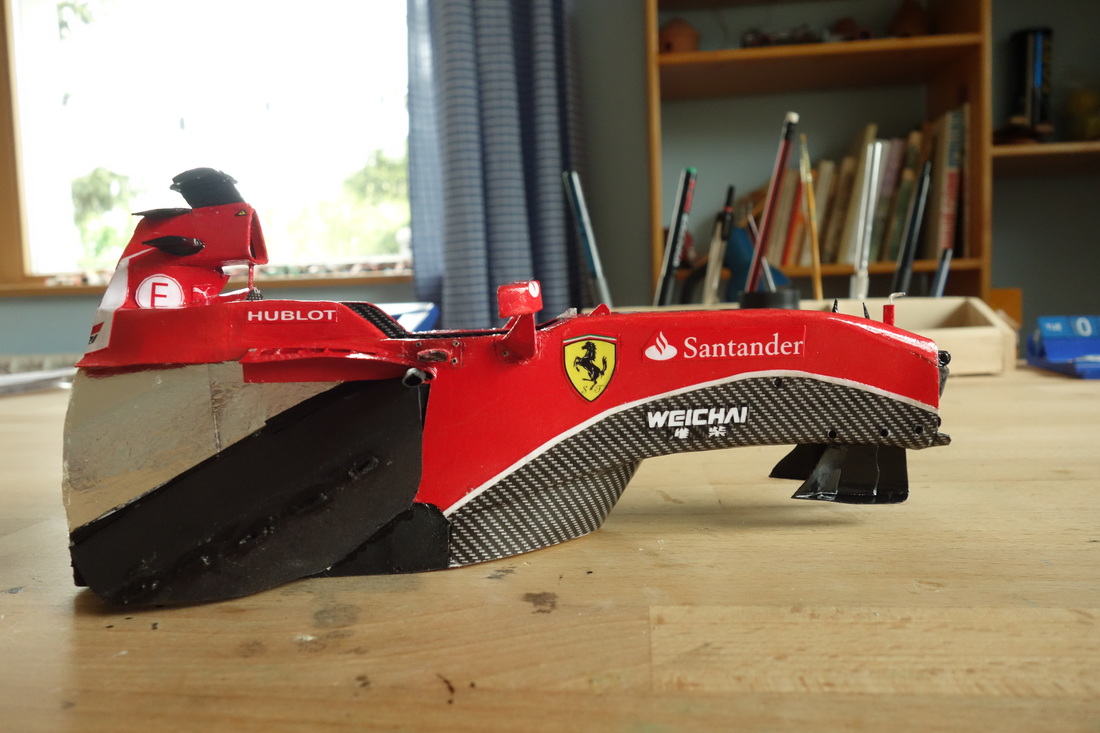
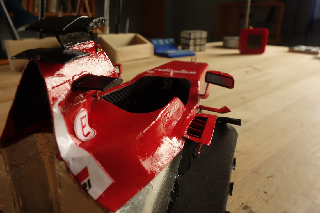
I have to admit I was initially a bit scared of building the bodywork. It is such a large area that determines how the whole car looks and any asymmetries or less-than-perfect fits could be disastrous. However, this also means that due to its size, it’s one of the areas which are most satisfying because of high bang-for-buck (or in this case, effort) ratio. I started with the top section. I had to take the fin and the mounting points to the airbox (the front end) into account. Also, I had to make sure that the cardboard on both sides curves towards the middle; the shape had to be smooth. The sidepods were trickier and required more prototypes to get right. I used the same technique that was extensively described in the suspension report (rear bodywork). Also, I had to rework the floor a bit to ensure a good fit at the front end. Luckily, this alteration was quite precise and now the vertical limiters on the floor hold the bodywork well. The vertical elements that attach to front floor end were not difficult to make. They are connected to the floor flap via two metal rods. Once I got their shape and position right, I glued them to the sidepods. The white line is something I came to appreciate: a cool design feature which, if you take a close look at a side view of the car, runs from the front wing right to the very edge of the rear wing in roughly the trajectory of airflow (check out Chainbear’s video on f1 livery). Applying decals and varnishing was extremely satisfying. It just changes the look of the whole car dramatically and it suddenly stands in front of you in all its glory (almost); it’s a completely different object compared to its previous naked self. The only suboptimal area is the leading edge and the Claro logo: the thickness of the cockpit bodywork that matches is different and the fit isn’t perfectly smooth. Overall, I’m pretty happy with the outcome. I managed to get the shape and stiffness of the bodywork such that it fits relatively well without help from glue or additional structural pieces. To remove the panels, I have to detach the sidepods first, then pull upwards and backwards at the same time. Of course, I’ll try to not do this too often, as the cardboard might weaken at some critical contact points. Also, take a look at how the Shell logo and some cardboard sanding almost completely hid the slot that was necessary to achieve the curvature. |
|
|
Steering wheel
I tried to start with a rough approximate of the 3D shape, formed with layers of 1mm thick cardboard. It also includes a hole where the hollow axle will be attached. I then covered the basic shape with carbon and made the axle with its gear shifters. Mounting it, however, was postponed for later as I needed to be able to glue all the details first. Luckily, I found an accurate 3D model of the steering wheel which helped immensely with deciding exactly which knobs to feature, how to simplify them where necessary and what to leave out in a bid to increase build quality. After some fiddling on Adobe Illustrator and a very high-quality printer which rendered even 1mm diameter circles with text inside, I mounted the display and knobs pretending to be a watchmaker. Here’s the result, once in my hand, once next to a 1Euro coin for size reference. |
|
|
Seat
|
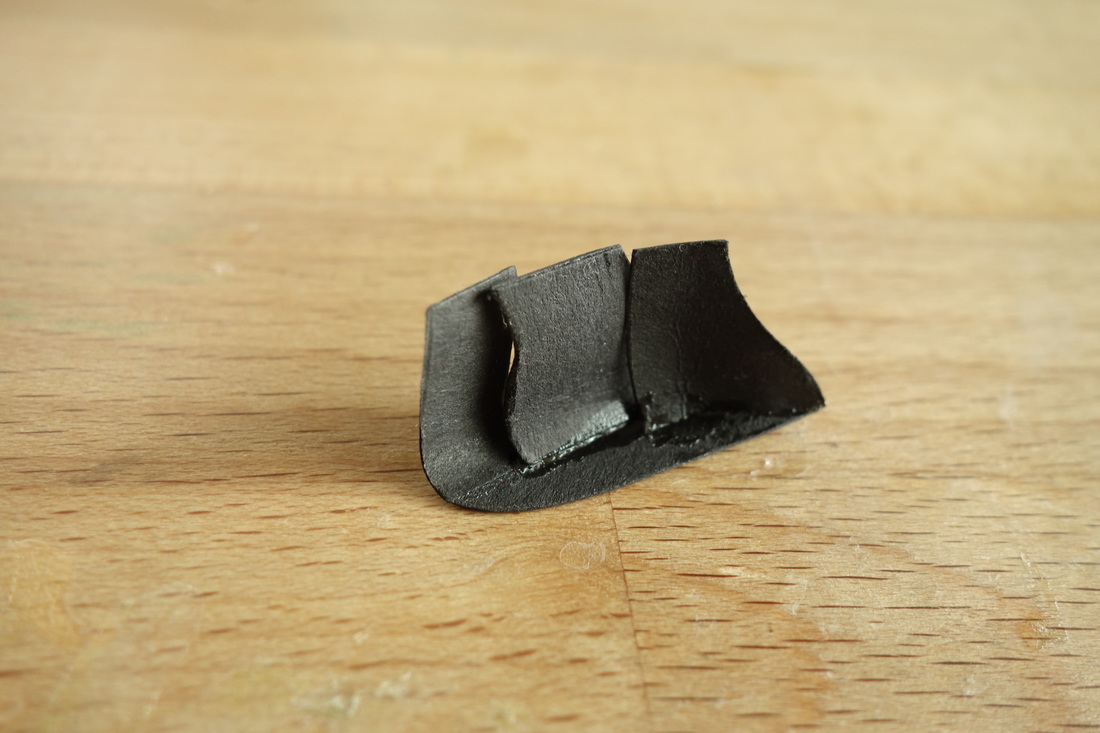
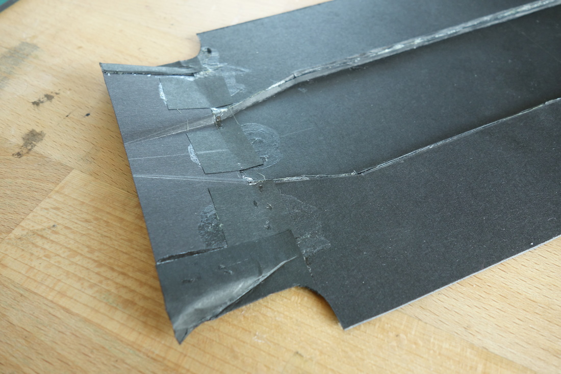
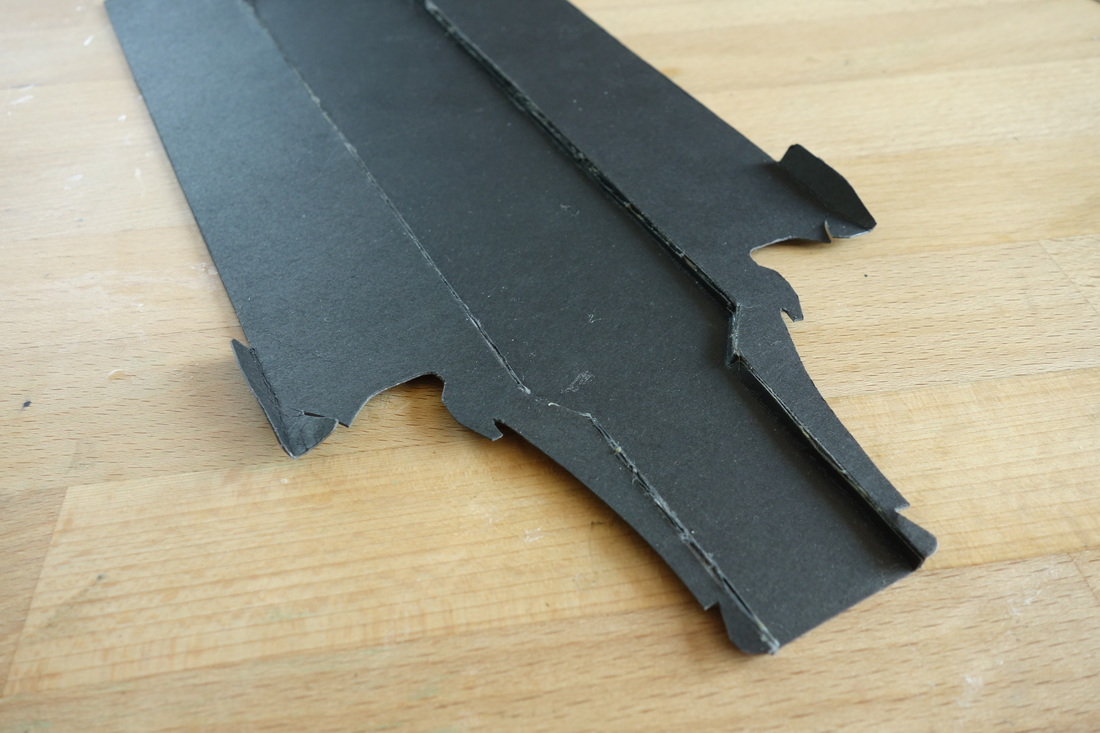
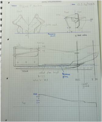
The final component of the whole car came to be the seat. As is with all internal components, unsurprisingly few photographs are available. So I had to build using mostly “common” knowledge, basing the shape on a Scarbs’ drawing. As the seat is a complexly curved object, I decided to use a “mold” to define the geometric boundaries, using simple 2D shapes.
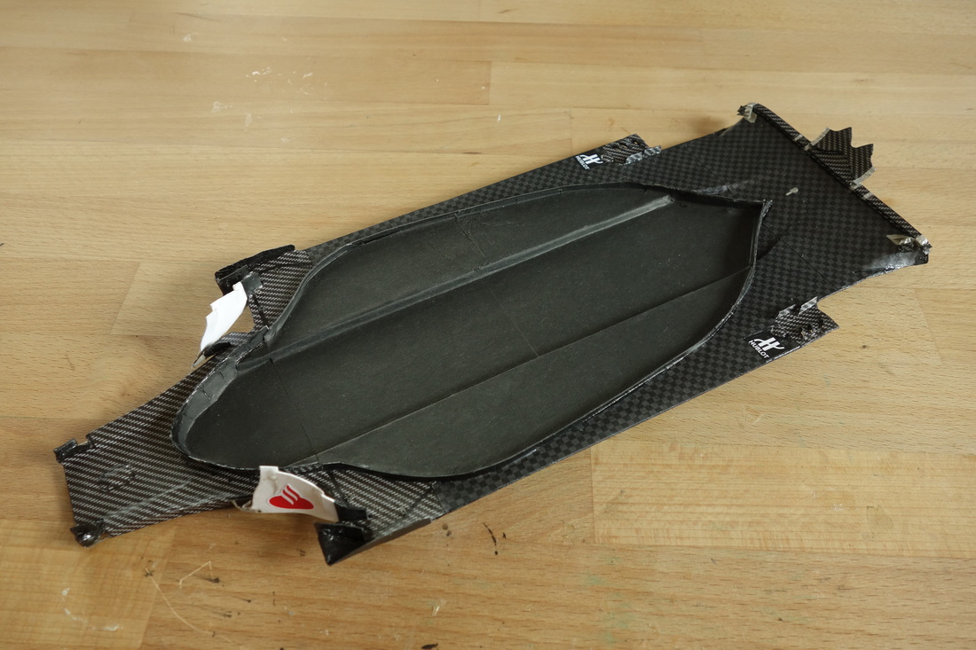
I then used one main piece of black card with many vertical slots on its sidewalls to form the seat itself. I then reinforced said sides with further material and sanded the edges, fitting it every now and again to the jig to ensure fit. Carbon fibre coating came next. Nothing too different here; probably just the fact that coating convex shapes is slightly trickier that concave ones: the glue I use for large surfaces, Moment Kraftkleber, does exactly what it says on the tin: it sticks instantly, which means once the two parts come into contact anywhere, their relative position can’t be changed anymore. This makes alignment tricky. Finally, the seat belt system. Contrary to expectation, this was great fun to do. |
Thanks for viewing!
